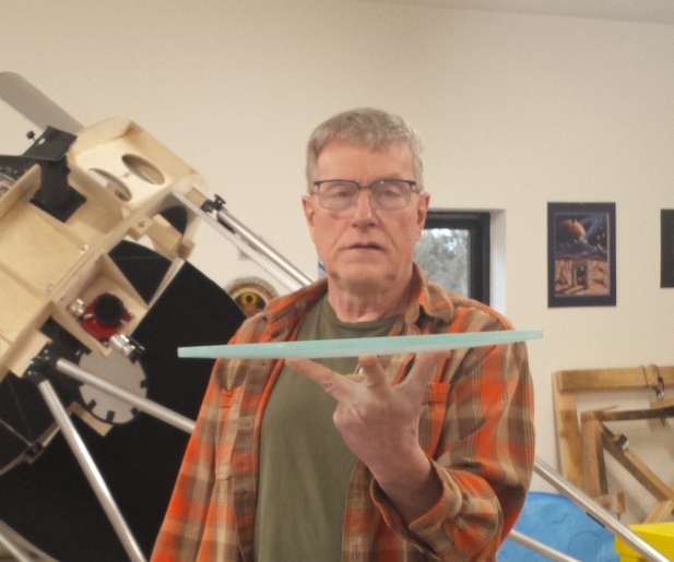
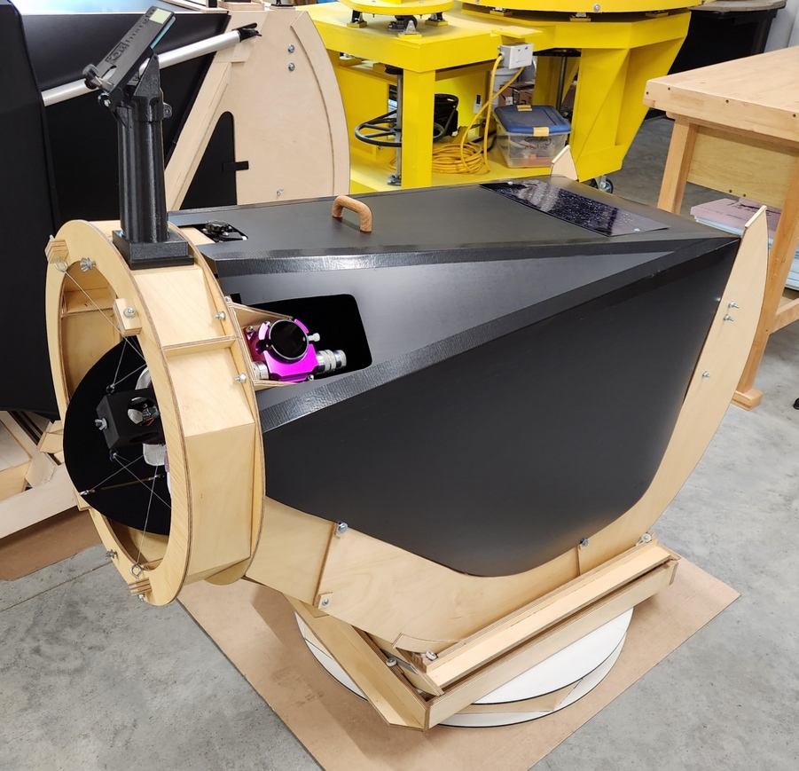
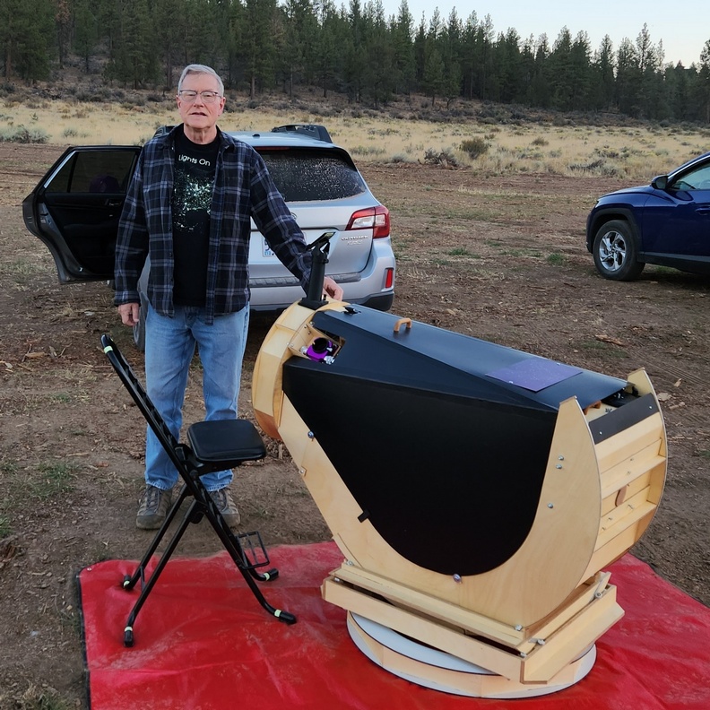
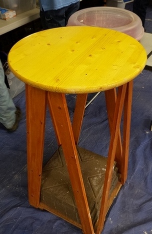
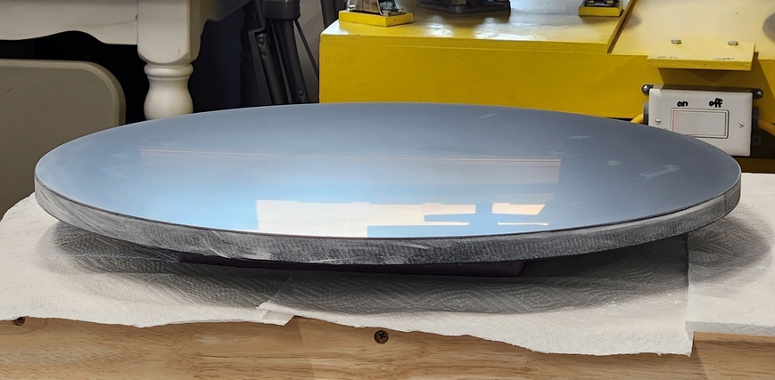
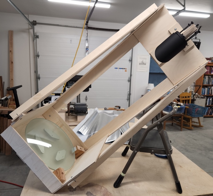
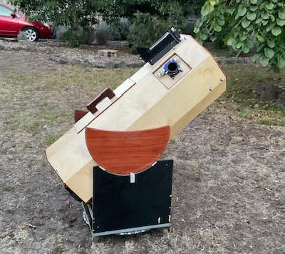
My 16.25 inch F2.9 x 3/8 inch thick mirror and scope, 2022.
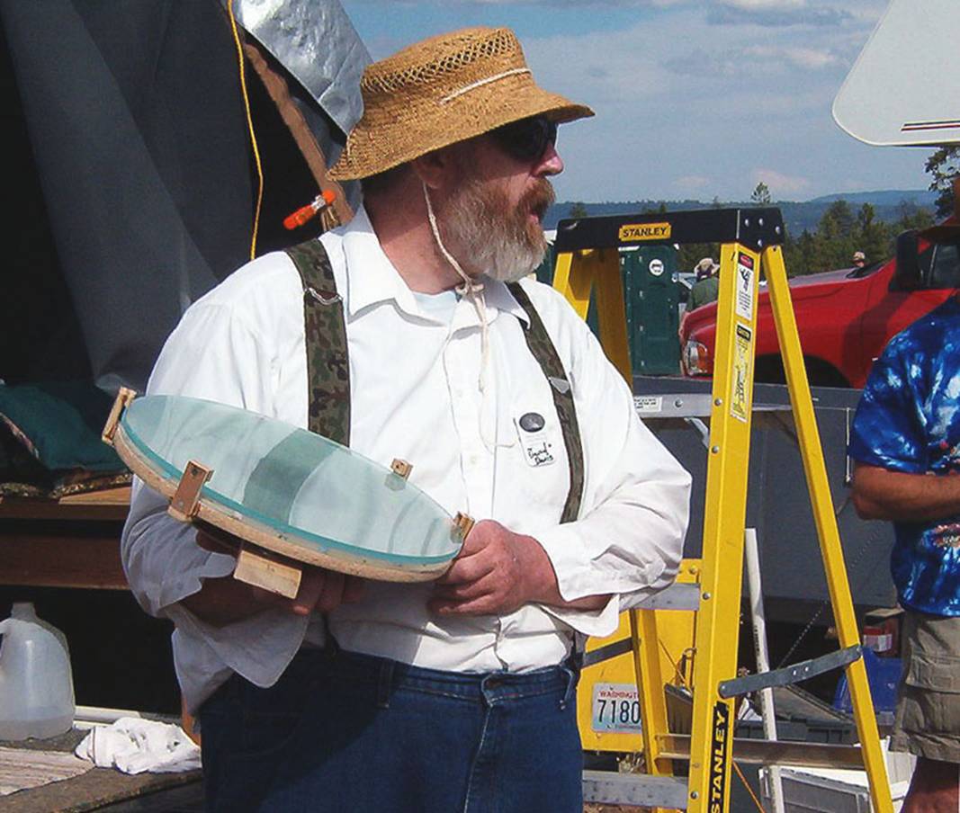
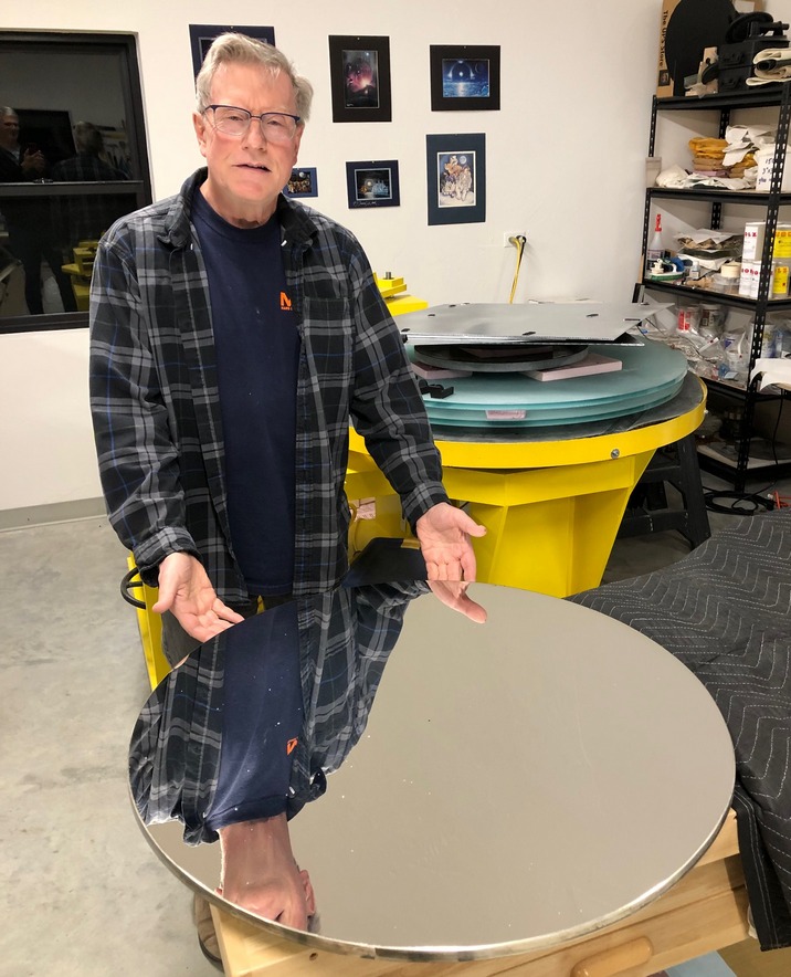
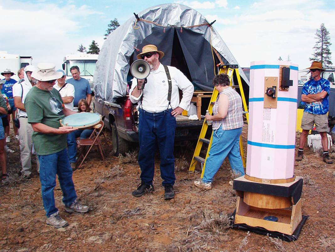
David Davis with the first ultra thin meniscus mirror, a 16 inch F3 x 3/8 inch thick, at the 2005 Oregon Star Party Telescope Walkabout.
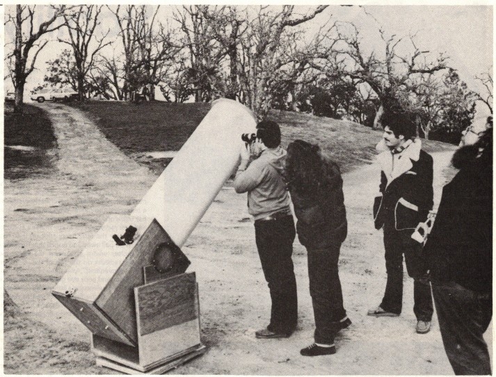
My 16.25 inch F2.9 x 3/8 inch thick mirror and scope, 2022.
For comparison, the first standard Dobsonian design, the San Francisco Sidewalk Astronomers 16 inch F5 by Earl Watts, Bob Kestner, Doug Berger, et al, as popularized in Richard Berry's Telescope Making magazine.
First up:
If mistakes are made, and they can be, then materials needed will increase depending on how much backtracking is required.
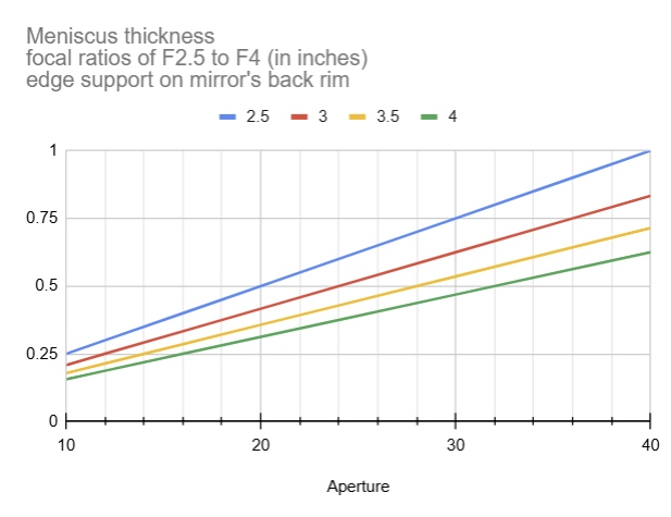
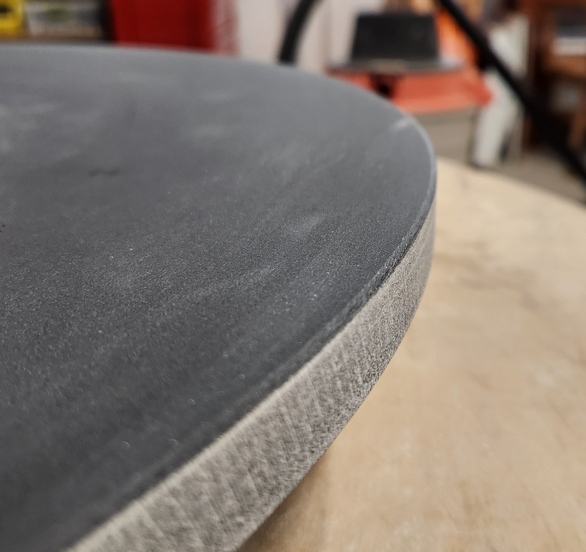
Supporting meniscus mirrors work best when the edge support is at the mirror's center of gravity. The thinnest a meniscus mirror can be then, is the saggital depth which puts the mirror's center of gravity on the rim's back edge. Though successful thin meniscus mirrors have been supported by a plug through a central perforation.
There are other reasonable grit sequences. For example, skipping 500 SiC and going to 25 micron AlO2 followed by 15 micron and 9 micron. Whatever grit size is chosen for the switchover from SiC to AlO, be sure to start the AlO sequence at the same size that the SiC sequence ends. AlO is smoother shaped and softer than SiC, causing far less damage to the glass than SiC. It's action on the glass is similarly finer. SiC leaves lots of microfractures that the AlO has to plane down through.
See Zane Lander's spreadsheet of materials and costs.
GotGrit has grinding kits. Grit kit (grits only) and grinding kits (includes dental stone and tiles).
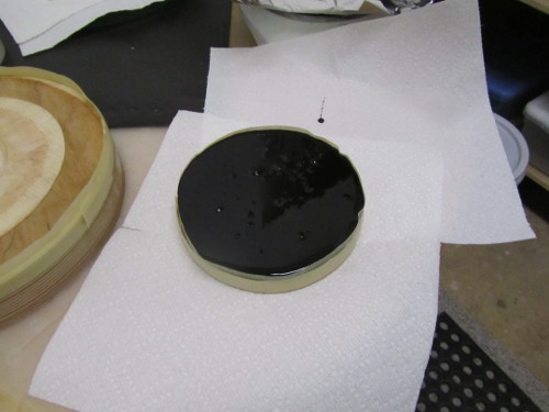
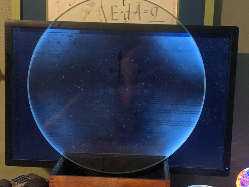
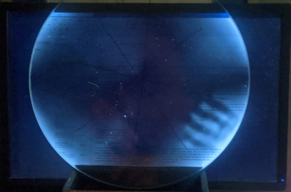
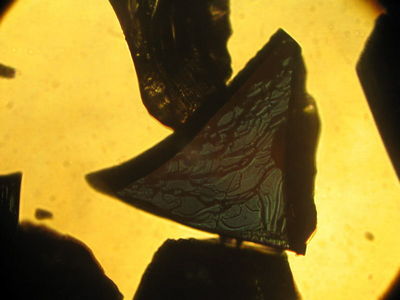
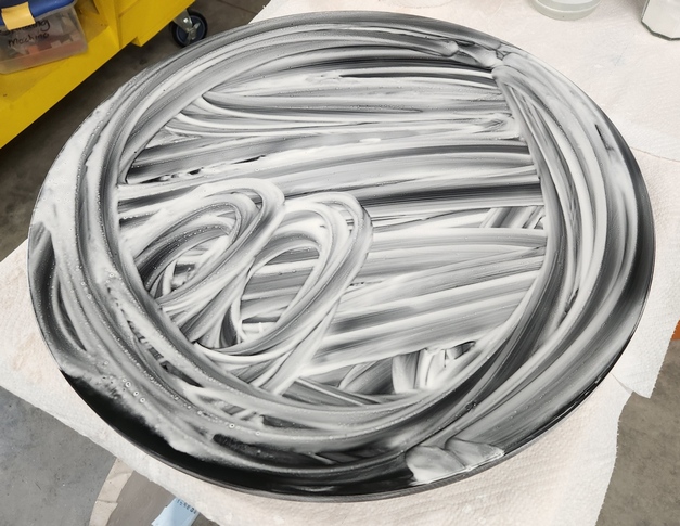
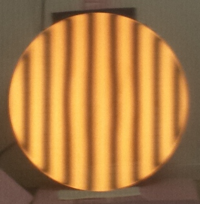
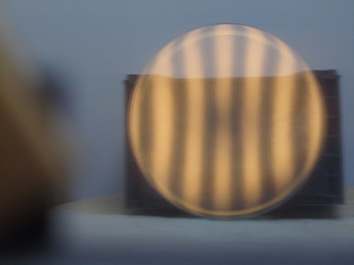
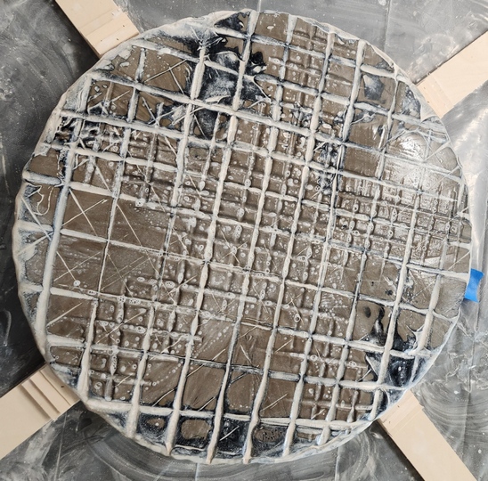
The pattern shows mild strain, accentuated by the camera. You can see birefringence stress induced by the two-point edge contacts where the glass meets the wooden box. Simply grabbing the mirror for a couple seconds leaves a heavy hand print in crossed polarized light. This mirror parabolized easily and exhibits a surprisingly stable star test during dropping evening temperatures.
I use an old printer stand that I can walk around. Possibly a work bench. If you cannot walk around it, then you will have to rotate the work every minute to simulate working the mirror as if you are walking around the work stand. Maybe a piece of plywood with very sticky feet on a sturdy table. The lateral forces pushing on the stand during polishing and parabolizing are considerable - all that you can muster to push the mirror across the pitch lap.
Grinding is messy and loud. Ideally you have a work area other than the kitchen table or counter. Expect to mop the floor. Use a piece of plastic underneath the work. And a bucket to wash your hands in.

John Dobson used a wooden plank stretched across two blocks. You sit on one side and place the work on the other side. Be sure to rotate the upper piece every few strokes and rotate the bottom piece every few minutes or every wet.
See how I fine ground my mirror. My webpage on fine grinding.
We use two grit types: silicon carbide grit and aluminum oxide powder.
SiC as seen in a microscope, courtesy Jerry Oltion.
I recommend that you match up your final silicon carbide grit size with your first aluminum oxide grit size. It is like stepping down in grit size by 3x, the amount of sub-surface damage caused by silicon carbide.
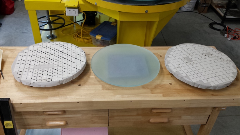
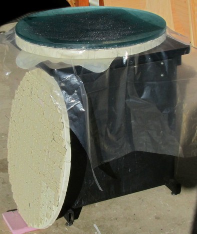
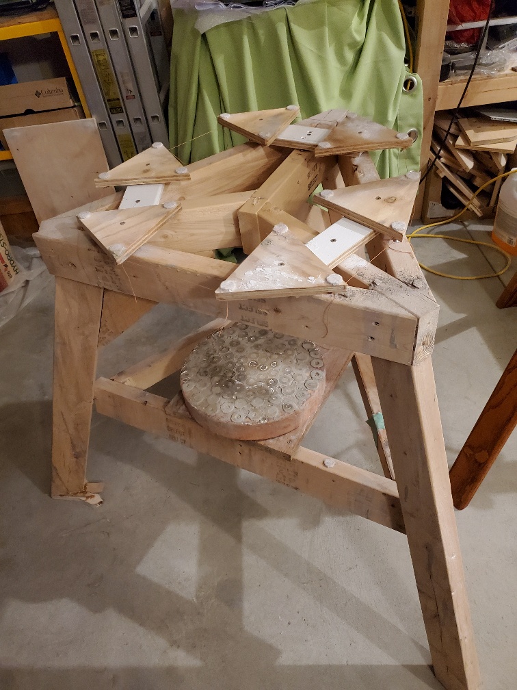
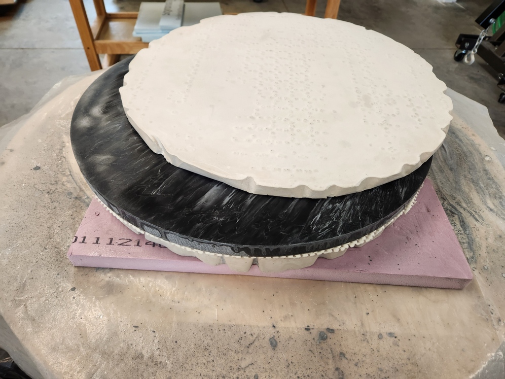
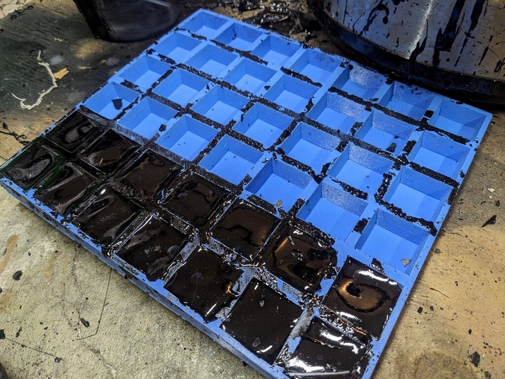
Make a tiled grinding tool from Hydrostone or similar. Thin plastic over the mirror, paper dam surrounding the mirror, unglazed ceramic tiles in their webbing cut to fit, a little spray adhesive on the tile faces to keep the tiles stuck down to the plastic so that they don't float upward in the Hydrostone, mix up the Hydrostone per instructions with a power mixer, pour into the mold. Begin grinding the next day.
At first the tool and mirror will grab. Keep rotating the upper piece 15 degrees every six strokes. And if the mirror is face up, rotate it 15 degrees every 15 minutes. Use lots of water. Eventually the grinding action will smooth out and the wets will last longer.
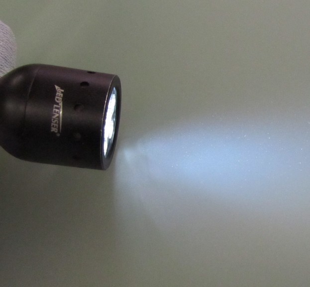
Use a focused strong flashlight, looking for the largest pits and scratches. Mark them with a marker on the mirror's backside, or make a mark on the mirror's edge, then record distance inward in a notebook. Grind until the largest pits are gone.
| Grit | Size (inches) | Removal rate (thousands of an inch per hour) |
|---|---|---|
| 60 SiC | 0.01 | 6.5 |
| 80 SiC | 0.065 | 4.3 |
| 120 SiC | 0.004 | 2.7 |
| 180 SiC | 0.003 | 2 |
| 220 SiC | 0.0025 | 1.7 |
| 320 SiC | 0.0012 | 0.94 |
| 400 SiC | 0.00087 | 0.77 |
| 500 SiC | 0.00075 | 0.71 |
| 600 SiC | 0.00063 | 0.64 |
| 25 AlO | 0.001 | 0.43 |
| 20 AlO | 0.0008 | 0.35 |
| 12 AlO | 0.0005 | 0.22 |
| 9 AlO | 0.0004 | 0.17 |
| 5 AlO | 0.0002 | 0.09 |
We can conclude that if we use a reasonable sequence of grit sizes that all grit sizes will take the same amount of time. We just need to establish how long the initial grit size takes.
It is too easy to over stroke while grinding. A stroke that maintains the sagittal depth and thus the focal ratio and focal length is no more than a 1/3 CoC. That's a stroke length of +-1/6 the mirror diameter, Center over Center.
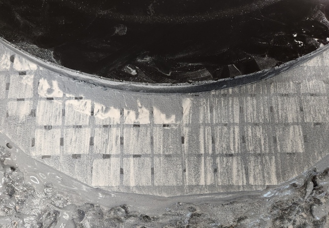
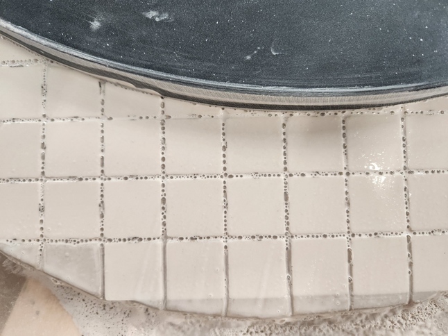
Counting 1 inch square tiles is an easy way to measure your strokes. For a 16 inch, the strokes should be +-2 1/2 inches or about two tiles overhang in each direction. The proper stroke length for a 20 inch is 3 tiles, shown here:
Turns out that straight strokes with no rotation can cause astigmatism in very thin blanks. This is what happens. A few straight strokes are made, creating a bias or astigmatism in the blank. Now, we count on rotating the mirror then repeating the strokes, averaging out the polishing action. But on a very thin blank, the initial bias or astigmatism persists because the glass rides up and over the pitch lap on subsequent strokes. Imagine the extreme case where a thousand strokes are made before any mirror rotation. Can that be averaged out? This is equivalent to removing astigmatism by the commonly taught stroke pattern, an asymptotic approach for sure. Therefore a continuous slow rotation of the mirror is best practice.
The steady periodic rotation of the mirror prevents low order or saddle astigmatism. And I've never seen Turned Down Edge (TDE) after flash polishing a fine ground mirror. TDE occurs during polishing. Flash polishing can be used at any stage of grinding. Create and press the pitch lap, attach polishing pads, then polish for 5 minutes. A faint reflection from the mirror's face can be seen in the mirror tester.
Extending the last wet can help with the next grit size, not so much to smooth the mirror but instead to better mate the mirror to the tool. The mirror and tool have different radii of curvature, the difference being the grit size. When going to the next smaller grit size, there can be initial stickiness, perhaps even scratches.
Imagine for ease of numbers that you are grinding a 10 inch F3. That's 30 inches focal length and 60 inches radius of curvature. And imagine that we are using 1 inch diameter grit! That makes the tool's curvature at 59 inches or a focal ratio of F2.95. Now imagine switching to a infinitesimally tiny grit. The mirror with its longer curve will teeter-totter over the tool. After grinding the two the new radius of curvature will be shorter than F3. The mirror's focal ratio, focal length and radius of curvature have shortened. Combined with Mirror on Top (MoT) grinding and the tendency of coarser grit particles to pool at the center unless the mirror is swirled often, this tends to shrink the focal ratio. Check your sagitta after a couple of wets with the next smaller grit size.
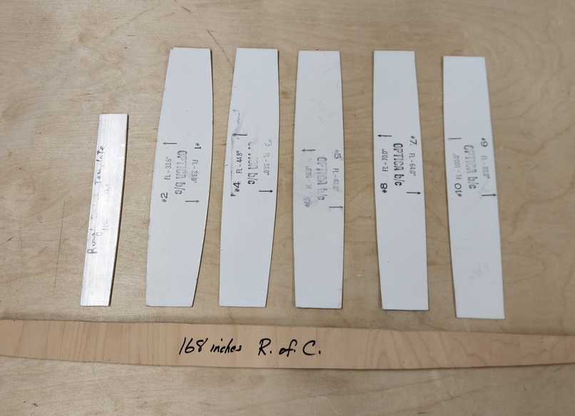
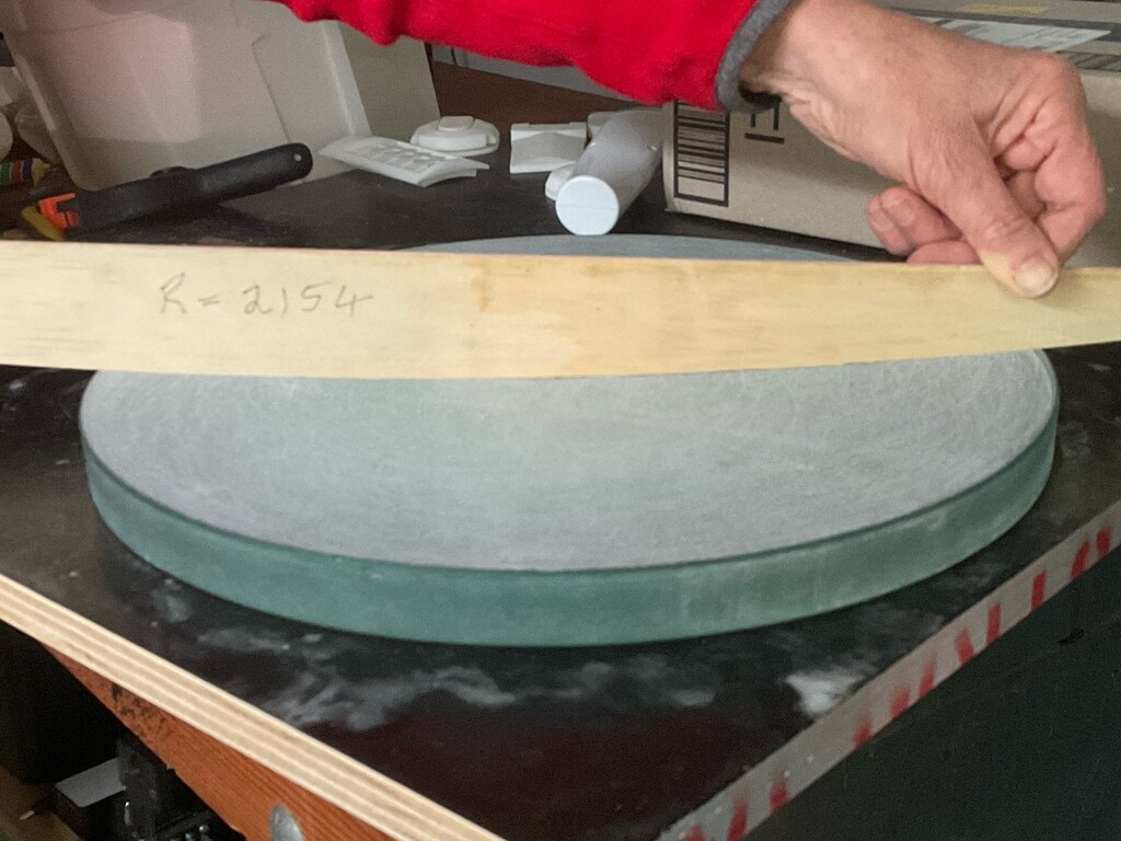
A great way to measure your mirror's curve is a template. Here a 14 inch F3 is being measured. A perfect fit! Keep in mind that the radius of the curve you cut is the radius of curvature which is double the focal length. This 14 inch F3 has a focal length of 42 inches or 107cm. Double that makes 84 inches or 214cm - the radius to cut.
Always maintain a bevel at the mirror's edge using a wet grinding stone. Always stroke downward to avoid lifting off glass flakes. Un-beveled glass will chip off with the slightest tap, even with ordinary grinding action. Bevel 1/16-1/8 inch wide [1-3mm] at 45 degree angle, round off the top edge.
A bevel can also prevent scratches. Particles can clump acting like a larger particle when dragged back across the mirror's edge. A bevel helps break apart the clumped particle.
Here is my 20 inch F2.7 beveled after 220 grit and the grinding stone wrapped in a diamond belt that I use by hand.

Soon, the mirror will glide back and forth across the tool. It's a great feel. Don't turn your back too long - the mirror might just slide off! If the resistance to movement goes up, then rinse off or wipe off the mud which is the ground down residue of grit, glass and tile. When the sound diminishes then the wet is over.
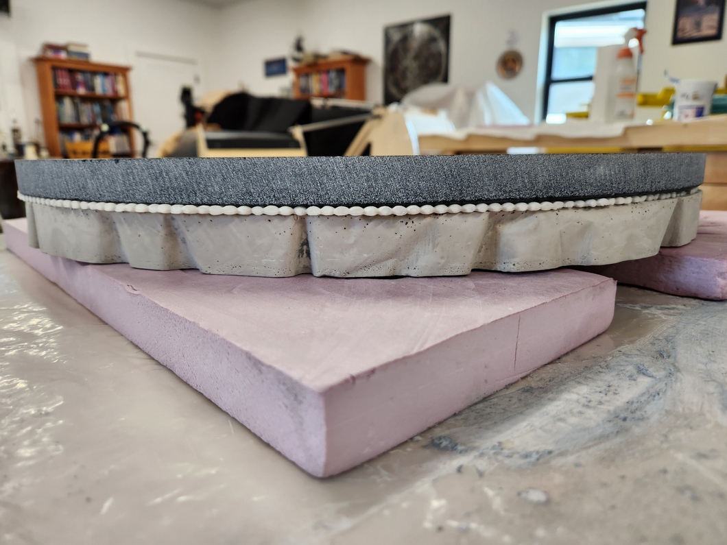
When grinding tool on top of the mirror, I use this stack from bottom to top: grinding stand, plastic sheet, rigid foam insulation, back side tool, non-slip kitchen mat kit into a couple of pieces for fit, mirror, then finally tool on top. I rotate the mirror a bit every wet to preclude astigmatism. Here's a 20.25 inch F2.7 during rough grinding.
The small size of aluminum oxide finishing powders call for special care.
Scratches can be a problem near the end of fine grinding and during polishing. Scratches can be caused by:
I go as far down into the finest aluminum oxide finishing powder grits as I can. Eventually I am stopped by scratches that occur more often than I can remove them. Small mirrors I've been able to get down to 3 micron. Most standard mirrors I finished with 5 micron, large mirrors at 9 micron. Thin large meniscus flex so I've had to stop at 12-20 microns. The downside is that polishing takes a bit longer, though not as much as might be judged from comparing grit sizes. This because grit sizes are a distribution of sizes centered on the named stated size. Damage from particles larger than the stated size must be polished out.
Jeff Baldwin finds that for slower f4.5 mirrors an overhang of 12.5% with a 3/4 sized tool is best. For faster f3 mirrors he uses an overhang of 16.7% which builds in some parabolization while polishing.
The make-it or break-it test is the flash polish test. If the mirror passes the flash polish test then there is every reason to contemplate a great telescope.
Heat the tool and the pads with a hot air gun before applying. Using a paper towel over the pads, burnish in the pads with say the handle side of a scissor. After use, if you see loose pad petals then use a hot air gun to stick them down again. After charging the pads, run them with a minimum of water, nearly dry.
I continue polishing out with the pads. Quicker than pitch, easier than pitch. However, I find pad polishing limited by pads coming off. I then switch to pitch for smoothing and parabolizing. Also pad polishing will not fix any non-spherical issues from fine grinding.
We want softer pitch. Make the pitch lap at least 3/8 inch [10mm] thick. Channel and microfacet the lap.
A good idea for making pitch laps is Rob Brown's pitch squares in a silicon mold, which harkens back to Texereau. He coats the tool with a thin layer of pitch (can be brushed on) so that the pitch squares stick with cold pressing.
See how I polished out my mirror. My webpage on polishing.
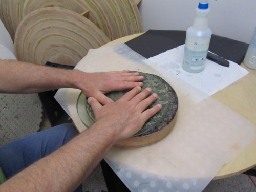
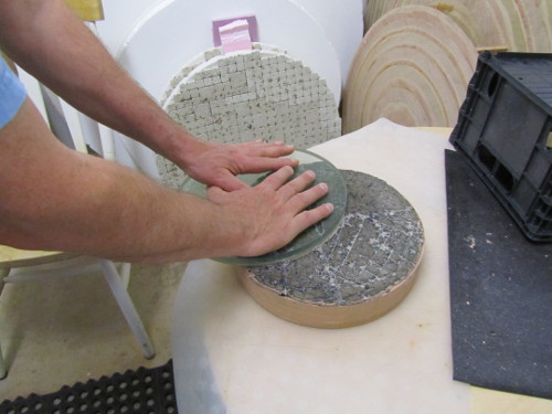
I grind, polish and parabolize with Mirror On Top (MOT) over a full sized tool. Additionally, I rotate the mirror slowly. The machine will rotate the mirror; by hand I rotate slowly while pushing the mirror back and forth. I also take care to start and stop in the same orientation.
The glass should feel warm to the touch after polishing, even radiating heat. Polishing is more effective when the polishing action generates heat. Go as long as you can in order to create this condition - an hour if you can manage.
Polishing is the hardest stage, taking lots of hours of heavy physical grunt work for large mirrors. A 16 inch [41cm] is doable by hand, even a 20 inch [51cm]. I did a 24 inch [61cm] once by hand - never again. For your second large mirror you may find yourself building a grinding and polishing machine!
Microfacet AccuLap using a wire brush under hot tap water followed by quick pressing to the mirror that is at room temperature.
Use a strong spotlight to search for haze near the edge and at the center. USe a magnifying lens while inspecting. Shine a laser nearly horizontal on the polished glass looking for haze with the naked-eye. Dried polishing agent on the mirror's surface can confuse the laser test. Another test is John Dobson's - if you see any shadow at all on the mirror's surface cast by fingers in front of a strong light (be careful if using the Sun because the mirror will focus the light) then you have haze that needs to be polished out.
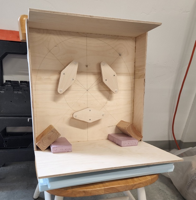
Build mirror cell to hold the mirror during testing. Also validates the mirror cell design. Can be the tube assembly or mirror box. How I built my test mirror cell.
Ronchi test shows smooth nearly straight bands.
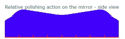
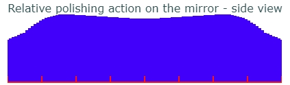
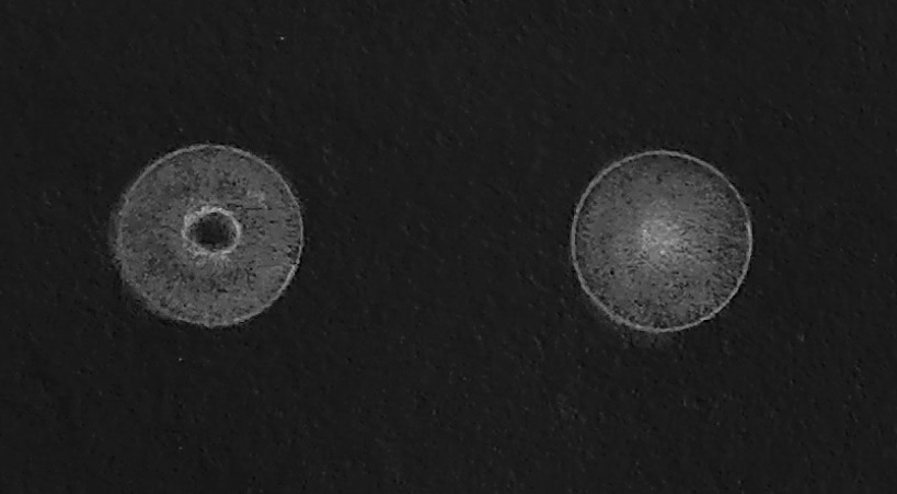
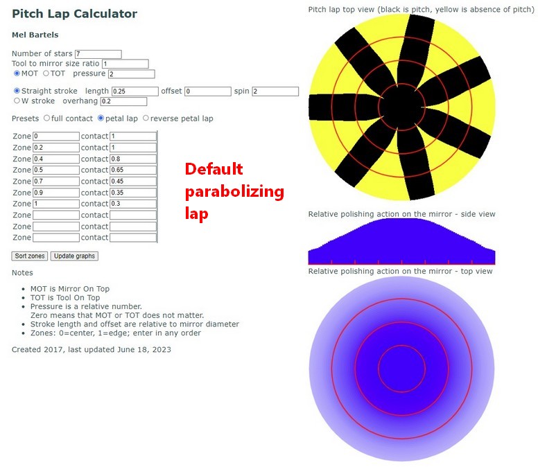
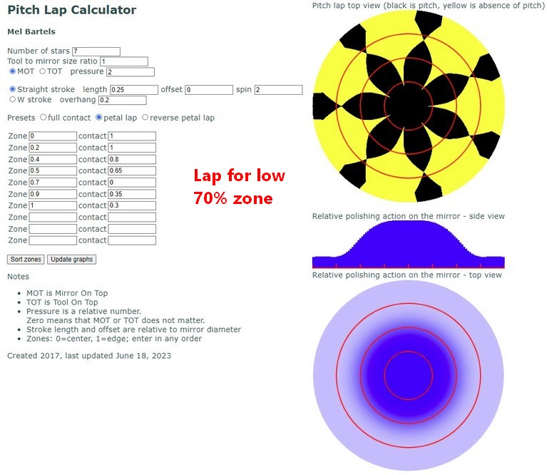
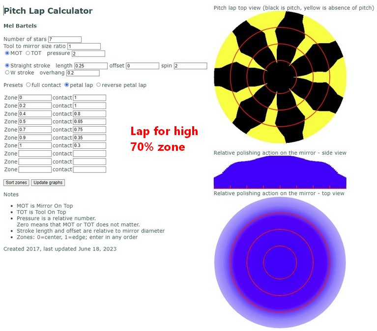
Amateurs often produce polished surfaces that are more oblate ellipsoid than spheroid. Often there is a rolled or turned edge (the last part of an oblate ellipsoid that disappears is the turned edge). We can see why this is by using my pitch lap calculator. In the left example we see that heavy pressure during polishing concentrates action on the 70% zone, tending to generate an oblate ellipsoid (high center, low 70% zone, high edge). And in the right example we see that light pressure during polishing leaves the edge lagging, tending to generate a Turned Down Edge (TDE). Both can be fixed straightforwardly by the application of proper pressure and stroke length. I work to make my mirrors perfectly spherical before parabolizing to demonstrate good control over the polishing action.
An oblate ellipsoid looks something like this in the Ronchi test when the grating is moved closer to the mirror such that the grating is inside the radius of curvature.
See my star test rig. My webpage on star testing and rigs.
Further tests that you can use:
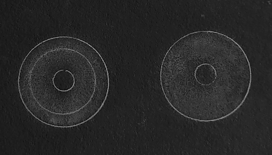
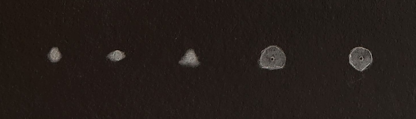
Failed snap focus: very faint glow surrounding star at best focus; lingering bright center as star is run through focus.
Turned edge (invariably a Turned Down Edge, TDE): fuzzy or hairy edge on one side of focus; bright ring on other side of focus.
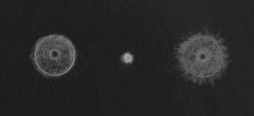
Over or under corrected (over or under parabolized): diagonal shadow does not break out evenly on both sides of focus; lingering central brightness on one side of focus.
Zone: bright ring on on side of focus; corresponding dark ring on other side of focus. Note how the zone moves from center to edge as the star image is defocused.
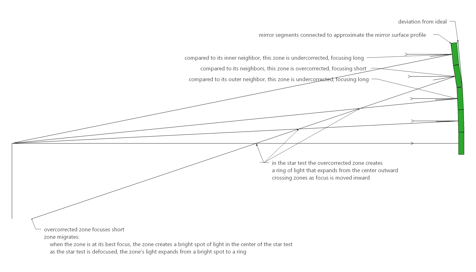
In large fast mirrors, a minor zone is acceptable. Note that their is no noticeable dark ring on the other side of focus indicating that the zonal deviation is slight.
Miscellaneous issues such as astigmatism and pinched mirror. If the astigmatism or deformation is aligned vertically with the telescope tube, then suspect the mirror cell. Rotate the primary mirror by 60 degrees and test again. Then rotate back to original orientation to verify consistency of mirror placement in the cell.
My Ronchi Calculator suggested that I was close, though not finished. What did my first star test result of the 16 inch F2.9 say?
See how I parabolized out my mirror. My webpage on parabolizing.
We adjust the mirror's face until it forms a paraboloidal curve, focusing light arriving from distant astronomical objects. This was sometimes called 'figuring' in the 1900's when amateurs used the Foucault test with a Couder mask and pencil and paper to calculate the mirror's ability to focus light.
Much of parabolizing consists of learning what to do: what works and doesn't work. Inevitably, we spend a lot of time on the first parabolizing attempt. When this fails we return to spherical and zip through the parabolizing much faster the second time. If only we'd known exactly what to do the first time. It's not unusual to return to spherical multiple times. It's best to think of the first parabolizing attempt as an orientation, learning and experimenting time. Then go for real the second time. For example, I spent 12 hours on my first parabolizing attempt followed by 5 hours to return to spherical after the first attempt failed. I finished the mirror in my second go-around in 4.5 hrs.
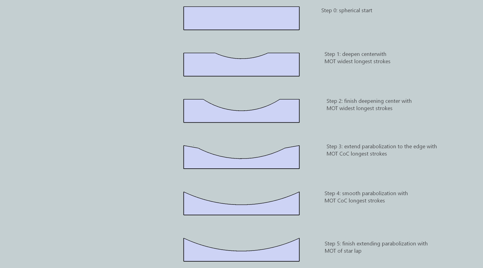
Parabolizing strategies: how to transition from spherical to paraboloidal. The rate of change of the radius of curvature increases as we move towards the edge of the mirror. Controlling and matching up to this increasing rate of change in the slopes of the outer zones is key.
Another factor is the difference between spherical and paraboloidal surfaces. The tool tends to return the mirror to spherical, making it hard to decrease the center's radius of curvature and keep it there. On the helpful side, the tool when pressed (formed to the mirror) assumes the reverse shape of the mirror. As the tool and mirror are stroked against each other, the zones where the radius of curvature changes dramatically rub preferentially.
Using my pitch lap calculator, we can explore strokes and pitch lap configurations that generate paraboloidal surfaces.
Here is the classic parabolizing method that worked for me on my 16F3. Note the preponderance of center over edge strokes compared to long center over center strokes.
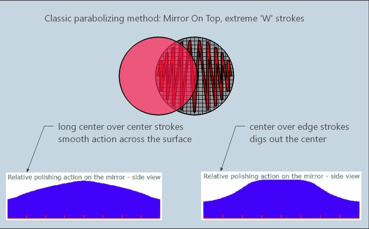
I spent 4 1/2 hrs of polishing time on my 16F3 for the second parabolizing attempt. Time spent in adjusting the pitch lap, pressing the mirror, testing and analyzing was considerably more. Much more time was spent on the first parabolizing attempt, learning how to parabolize this particular mirror size on this particular pitch lap configuration.
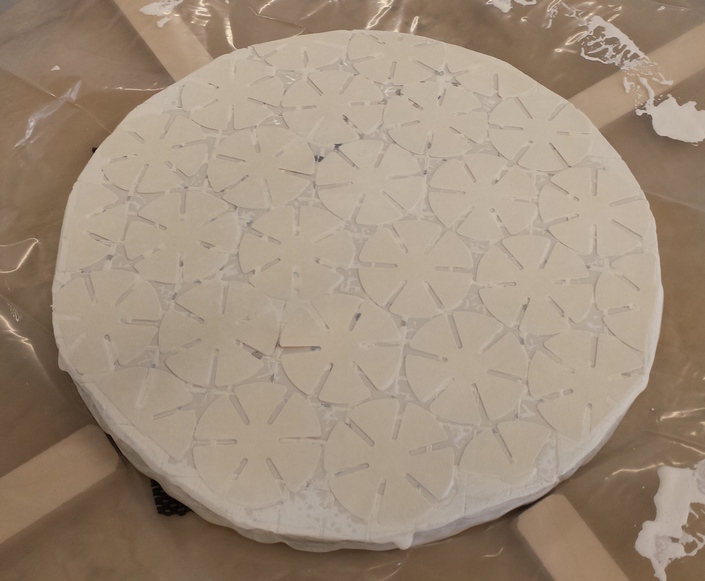
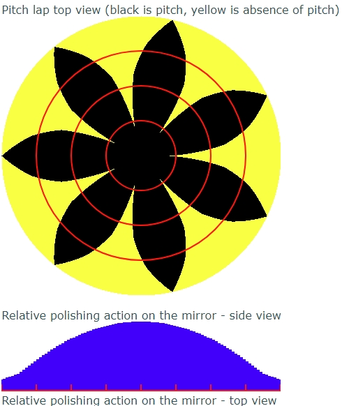
If this proves insufficient to dig out the center relative to the edge, then use a petal lap with center over center strokes. Here I created a five pointed petal lap using a short wood dowel to 'pop up' the pitch, the flat areas then no longer in contact.
The ideal parabolizing progression.
Getting the center 'low' enough, avoiding turning the edge, while dealing with zones, is the challenge with large fast mirrors.
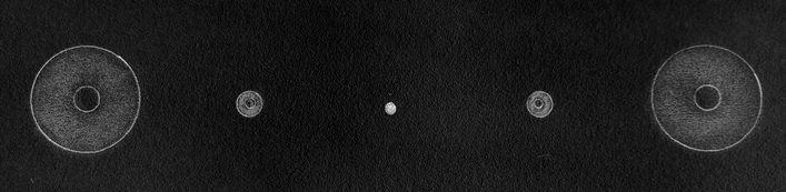
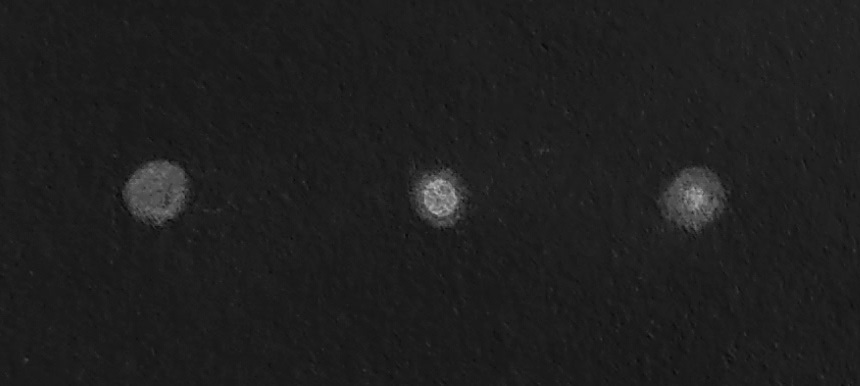
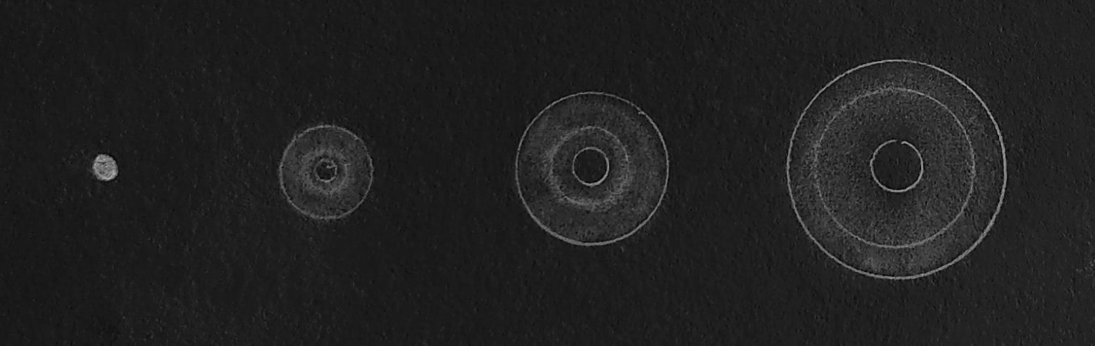
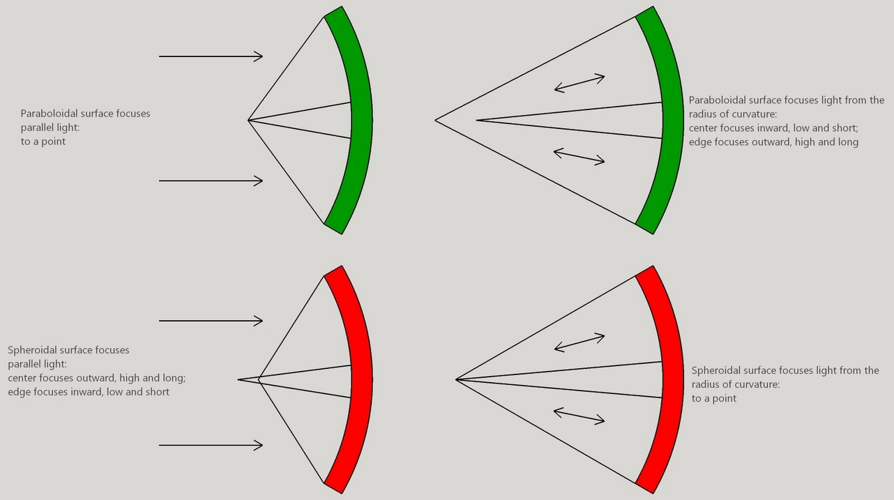
Two surfaces when ground or polished against each other, tend to form spherical curves. A spherical curve on the mirror's face results in a horribly failing star test, looking like this.
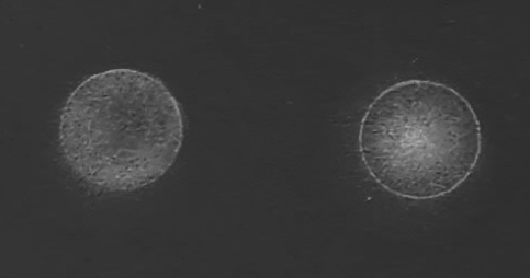
The edge of the mirror comes to focus inward, low and short, closer to the mirror as in the left hand star test image. The center of the mirror comes to focus outward, high and long, further from the mirror as in the right hand star test image. Sensibly parallel light reaching us from distant astronomical objects requires a paraboloidal mirror face.
A spherical surface will not work (except for small long focal length mirrors , eg, a 6 inch [15cm] F10).
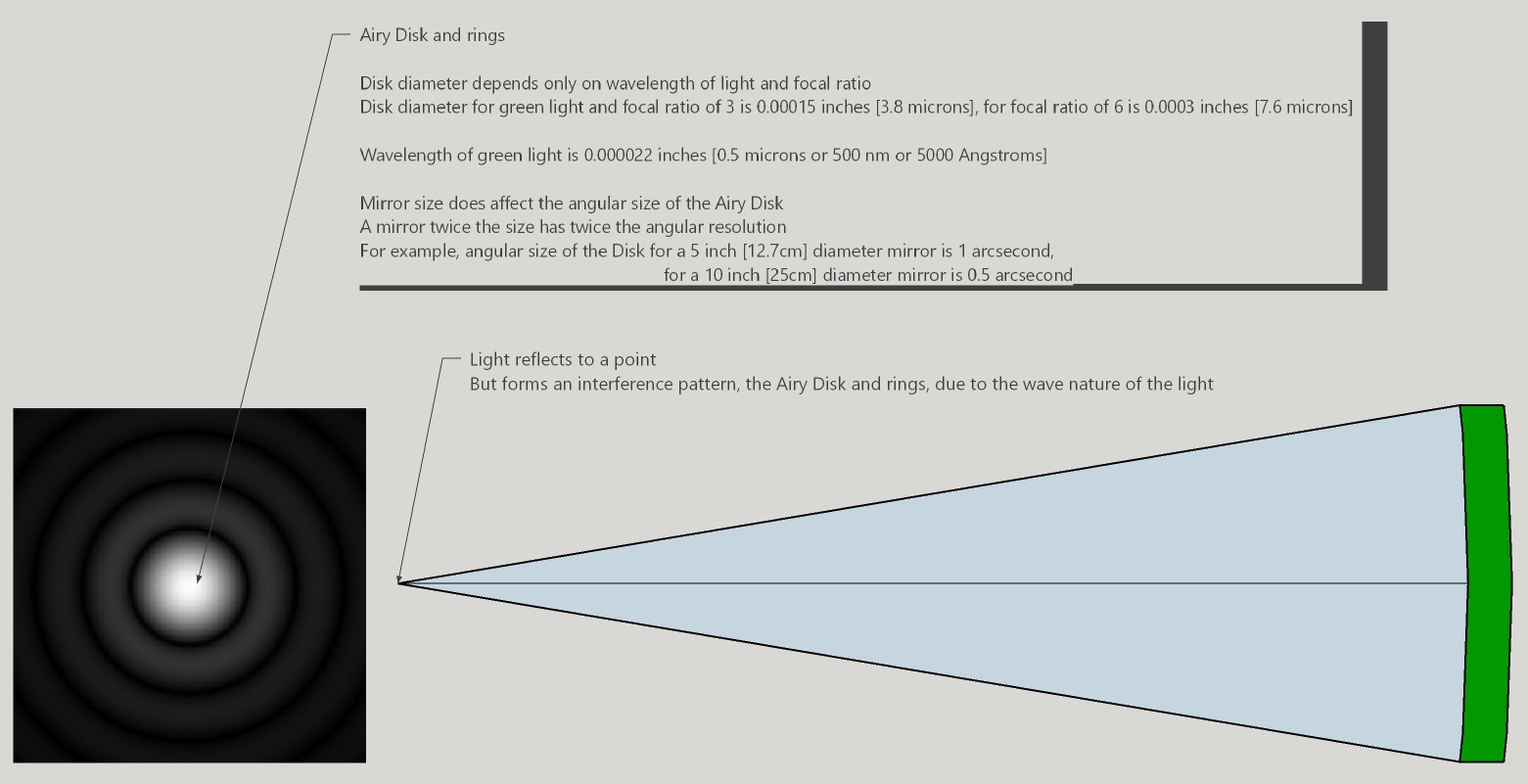
A paraboloidal mirror focuses parallel light from extremely distant objects to a point (with the consequent diffraction effects). The distance from the mirror to the focal point is the mirror's focal length. A spherical mirror focuses light emanating from a point back onto the point. The distance from the mirror to this point is called the radius of curvature. The radius of curvature is exactly twice the focal length. It is far more convenient to test indoors at the radius of curvature than outside at night, waiting for clear skies.
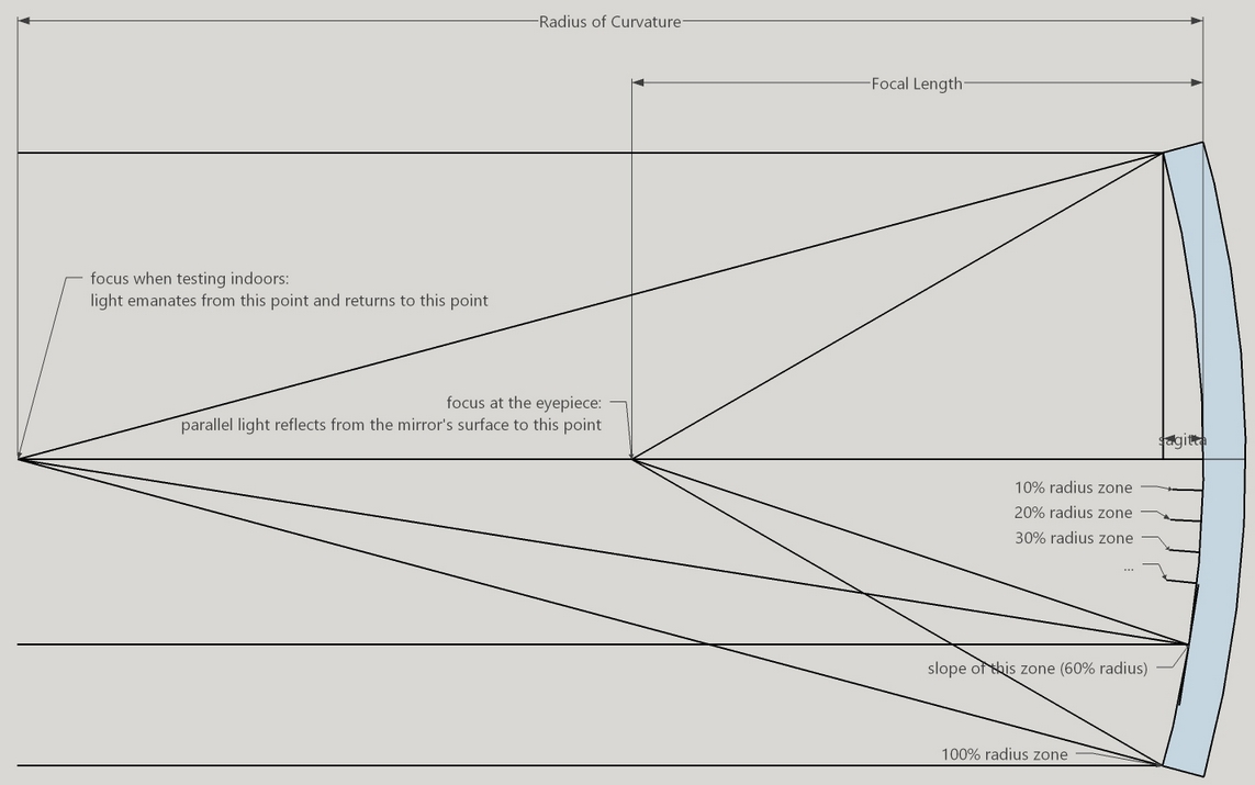
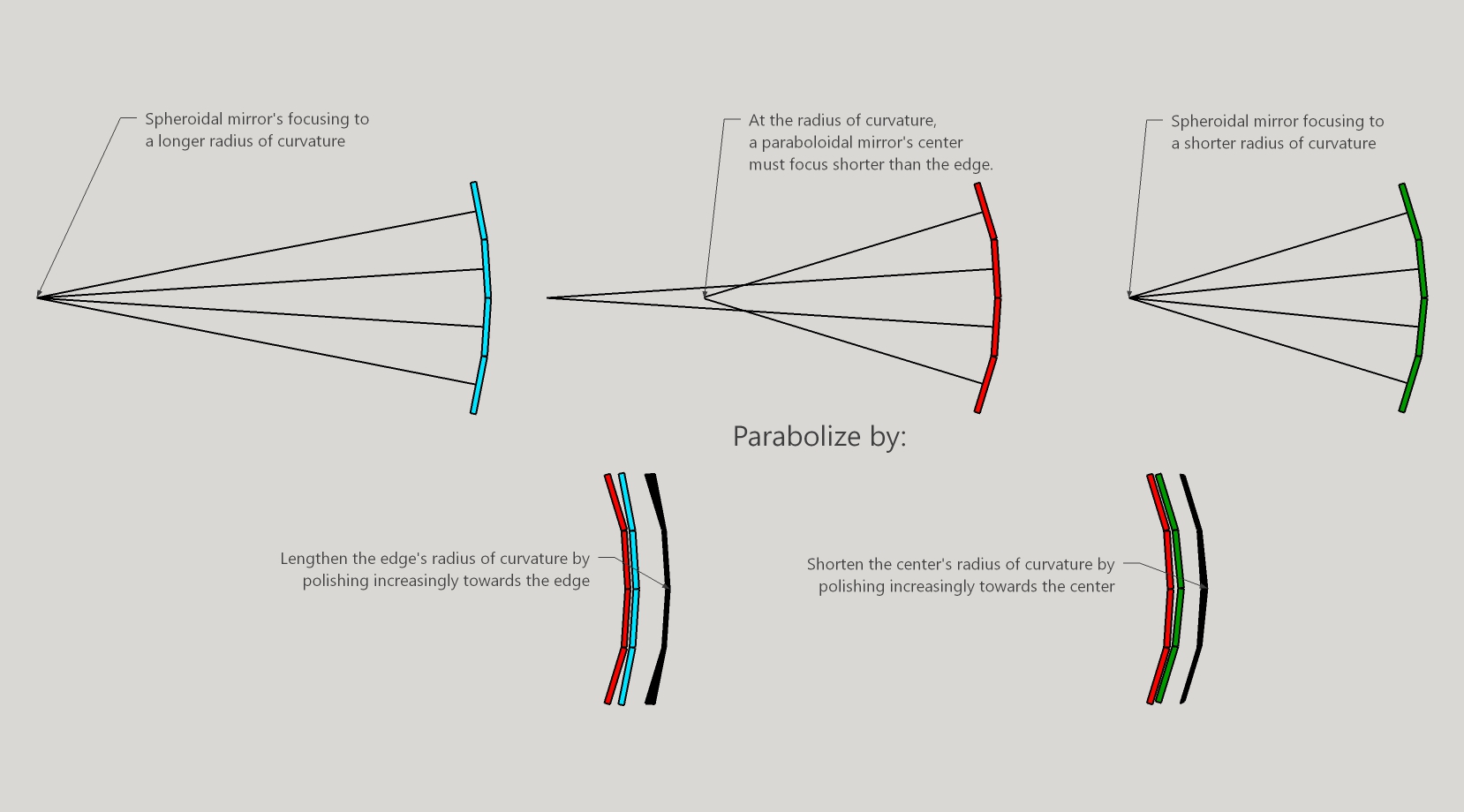
To move from a spherical surface to a paraboloidal surfaces means that we need to shorten the focus of the mirror's center, or lengthen the focus of the mirror's edge, or a combination of both.
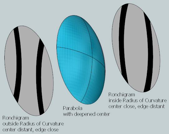
Conversely when light emanates from the radius of curvature, the required mirror face is spherical. Here a paraboloidal surface will reflect light such that the mirror's center returns light to an inward, low and shorter point as compared to the light reflecting from the mirror's edge. Light reflecting from the mirror's edge will appear to focus outward, high and longer than light reflecting from the mirror's center.
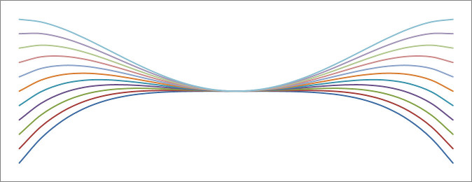
The difference between the ideal paraboloidal surface and the mirror's spherical surface depends on which focal length or radius of curvature we select. Here's a series of difference curves based on changing radius of curvature.
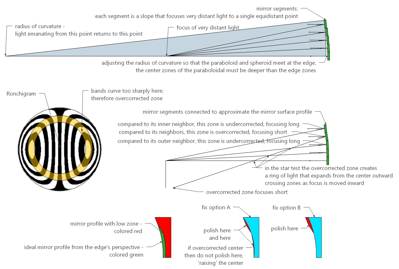
If we touch paraboloidal and spherical surfaces at their outside edge, then the difference in depth between the two surfaces is r^4/(8R^3) (r=mirror radius, R=radius of curvature). The mirror's center needs to be deepened by this amount. Or the edge needs to be reduced by this amount. Or if balancing at the 71% zone, the both the center and edge need to be reduced by 1/4 this amount.
Slopes can be calculated from the mirror's profile as measured by an OPD test. And the mirror's profile can be calculated from stringing together the zonal slopes.
Something magical happens when testing at the radius of curvature.
On the test bench at the radius of curvature the mirror's center and edge cross at different locations along the mirror's axis (the edge zones coming to focus a little beyond the mirror's longitudinal axis - the basis for the Caustic Test). The mirror can be divided into zones such as the edge zone or the center zone. I often divide the mirror into zones expressed as percentages measured from the mirror's center to the mirror's edge where the 0% zone is the center and the 100% zone is the edge.
As measured from where the mirror's center rays cross the mirror's axis, each zone should cross at a point r^2/2R, where little r is the zone's radius and big R is the Radius of Curvature (this is for a moving light source, for a fixed light source double the values).
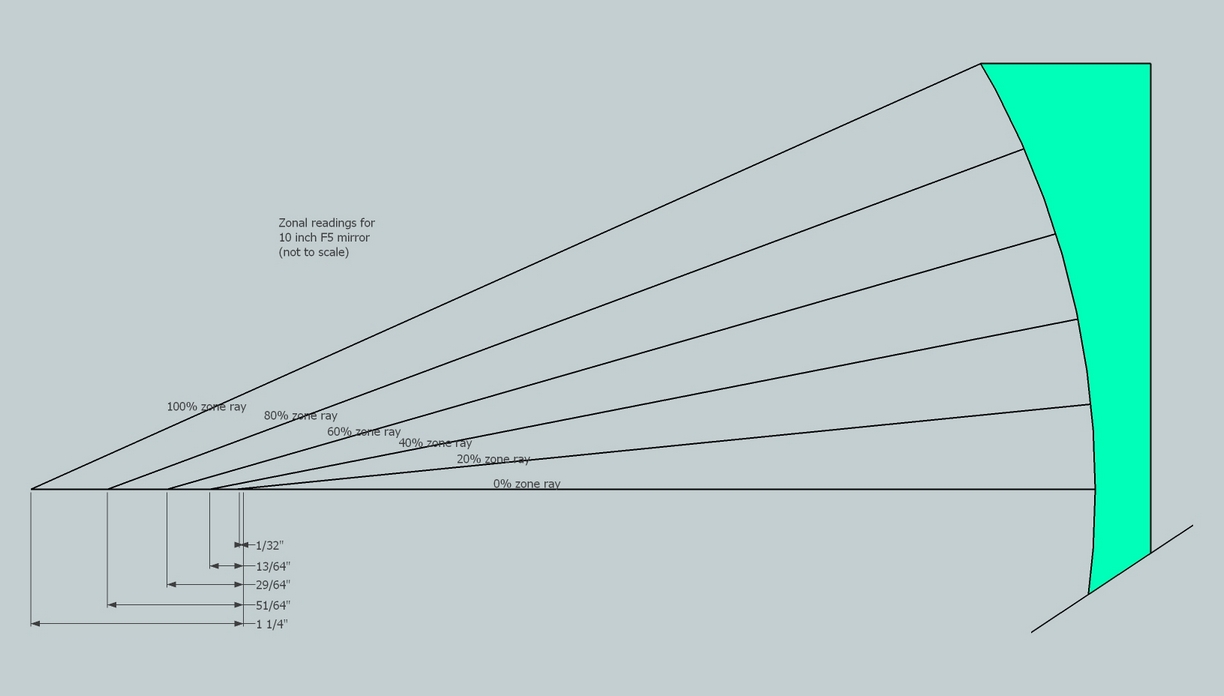
Consider the 10 inch [25cm] F5 as pictured. The parabolic deviation is 3.6 waves of green light. The zonal reading difference between the center and edge is 0.125 inches [3.2mm]. That is a magnification factor of 13,000 - an astounding situation that we take advantage of in our mirror tests! If we can read the zone's crossing point to 0.01 inches [0.25mm] then we could figure the mirror to 1/35 of a wavelength of light.
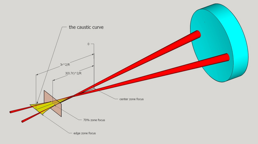
Here you can see the mirror's 70% zone focusing past the mirror's longitudinal axis. Each zone focuses along a curve called the 'caustic'. The first shadow and last light do not focus on the mirror's axis; instead the light comes to focus past the axis to the sides. These points have a displacement to and fro the mirror's face and also laterally, left and right.
Interestingly the caustic curve was first drawn by Leonardo da Vinci in the early 16th century who imagined that a mirror with such a curve would magnify light. Da Vinci came tantalizingly close to inventing the telescope. However he would have failed because his mirror would have been too coarse by a factor of thousands: he didn't know about the wave nature of light, that the wavelength of visible light is so tiny and calls for a commensurate accuracy of the mirror.
As with the star test where we can float the focal length in order to select for highest probability of success while removing glass, we can float the radius of curvature while changing the mirror's spherical shape to the required paraboloidal shape.
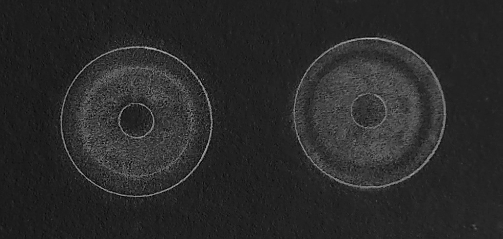
The difference between the two mirror surface shapes is easy seen and judged subjectively using the Matching Ronchi test and the Matching Ronchi tape band test.
I use the Ronchi test in two positions: inside and outside the radius of curvature.
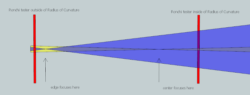
For a parabolized mirror when inside the radius of curvature the tester is closest to the mirror's center zones and furthest from the mirror's edge zones. And when outside the radius of curvature the situation is reversed: the tester is closest to the mirror's edge zones and furthest from the mirror's center zones.
Here's a favorite visualization of mine. The paraboloidal mirror is concave at the radius of curvature by virtue of lowering the center (or equivalently lengthening the edge). A grating placed inside the radius of curvature will see the center closest, the edge farthest. Since the bands expand closer in and shrink further out, the bands will appear fattened in the center and tapered at the edge. A grating placed outside the radius of curvature sees the center farthest and the edge closest, resulting in the bands appearing thinner in the middle and spread out at the edge.
Matching up the Ronchigram with the theoretical Ronchi bands takes experience and judgment.
Begin by matching the inside of radius of curvature grating offset (negative offsets). This emphasizes the mirror's central zones. As they begin to look good, switch to the outside of radius of curvature grating offset (positive offsets). This reveals edge issues.
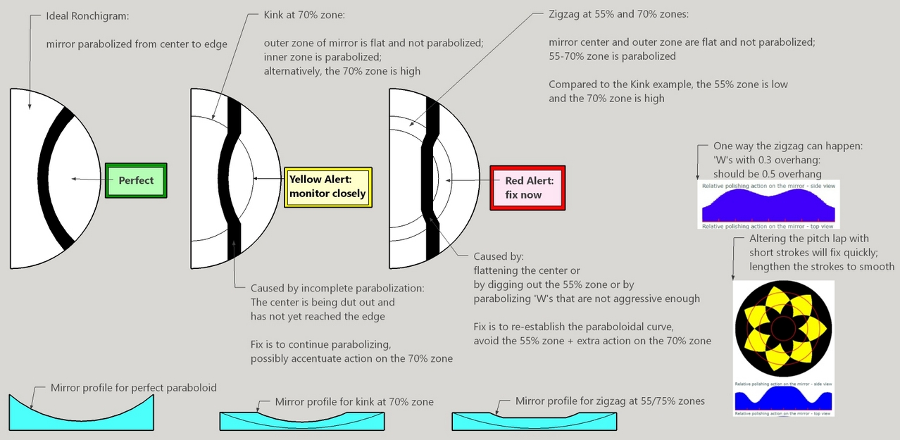
In analyzing the Matched Ronchigram, determine the priority issue to fix. Ignore secondary issues. For example, if the edge is turned, nothing else matters. If there's a bad kink, nothing else matters. If the mirror is grossly overcorrected, nothing else matters. Try to work on one issue at a time. We all want to try parabolizing strokes that magically fix all the mirror's problems at once. The problem is that this rarely works out, and when it does, we don't learn which stroke or pitch lap contact pattern fixed which issue.
Kinks (zones) appear when our actions are not smooth enough across the mirror's face and when the pressed tool is rubbed into the mirror's rapidly changing radius of curvature near the edge.
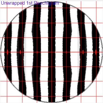
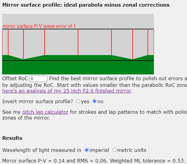
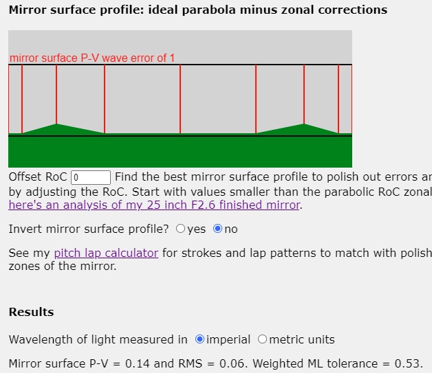
In the 'unwrapped' or software synthetic auto-collimation Ronchi calculator, a low (125% overcorrected) 72% zone looks like this when inside the radius of curvature. Note that the bands bow outward at the low zone, indicating overcorrection or a low zone that focuses short or below the focal plane. This for a 12 inch [30cm] F5 mirror. The error is 0.28 waves Peak-Valley at the focal plane and 0.006 waves RMS on the mirror's face. The weighted Milles-Lacroix value indicates that the geometric light rays pass through the middle portion of the Airy Disk.
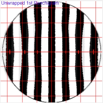
And a high (75% undercorrected) 72% zone using the 'unwrapped' Ronchi calculator looks like this when inside the radius of curvature - the opposite of the example above.
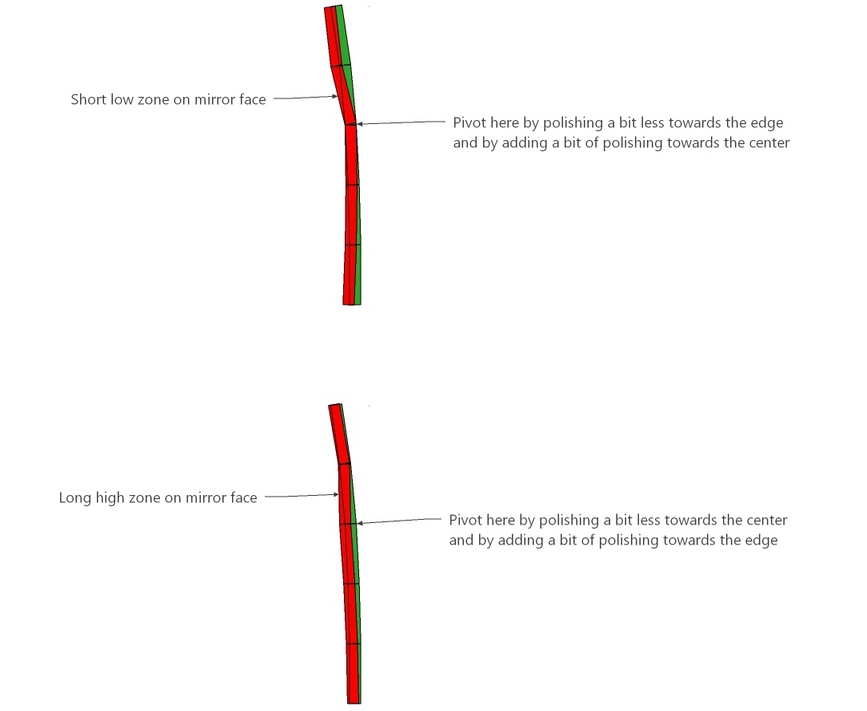
Fix low and high zones like this.
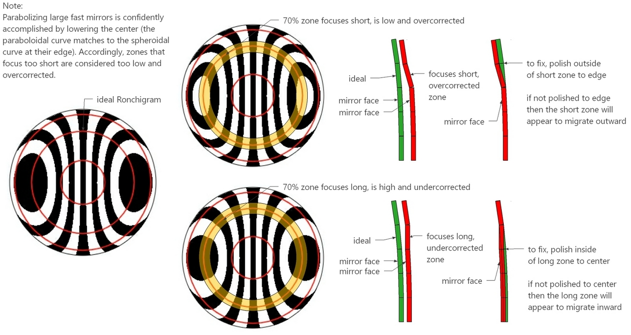
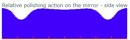
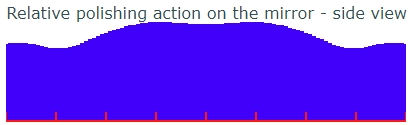
In particular, I like to pivot the work, bringing a bit of balance to polishing the mirror as a whole. The result is close to the dictum, "Polish the long and high areas; avoid polishing the short and low areas". The difference here is that for short low zones polishing should be emphasized just beyond the zone to avoid the zone appearing to migrate outward. And for high long zones polishing should be emphasized inside the zone to avoid the zone appearing to migrate inward.
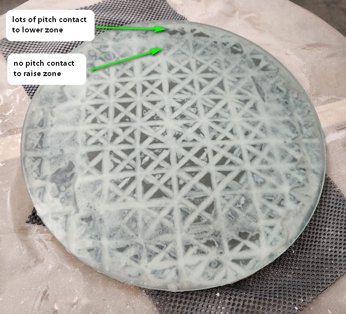
When using an altered pitch lap (pitch contact missing or extra pitch lap contact added), keep the strokes short to emphasize zonal action. This will tend to rough up the overall curve. Extend stroke length to smooth it all out (OK to leave altered pitch lap as is). Here are two examples, the first with 0.2 stroke length and the last with 0.35 stroke length: a big difference.
Here's a lap with a zone near the edge pressed out to fix a short, low and overcorrected zone.
Using a spider lap, correct low and high zones like this. Remember that short center over center strokes 1/5 long emphasize fixing the zone but at a cost of roughing up the paraboloidal surface while longer 1/3 strokes smooth the curve but act on the low/high zone slowly.
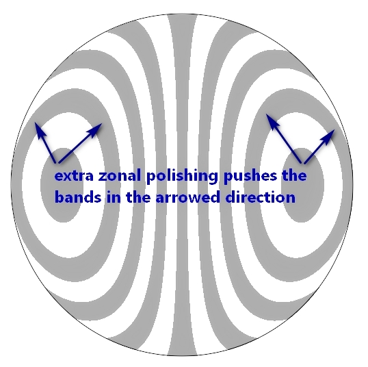
If in doubt, remember that extra zonal polishing pushes the Ronchi band in the arrowed direction; removing polishing action from a zone as just discussed pushes the bands opposite the arrowed direction.
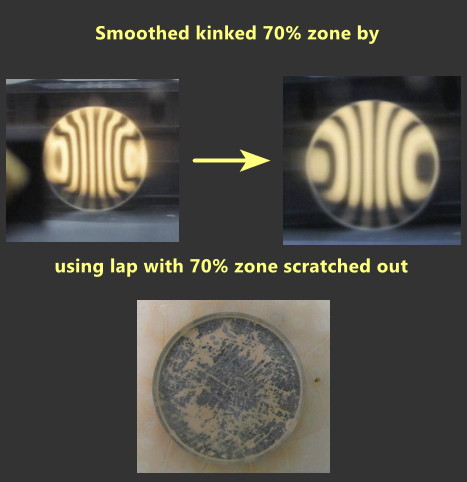
Here's a real life example of how I fixed a kinked 70% zone.
The dreaded zigzag occurs frequently with mirrors that demand large amounts of parabolization.
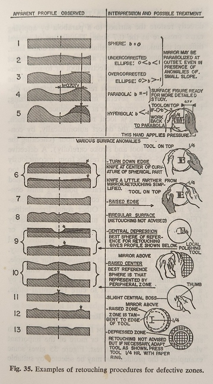
This is consistent with Texereau, How To Make A Telescope, 1963.
By chaining together slopes, the surface can be derived. The surface can also be calculated if an equation is fitted to the slopes. Slopes can be calculated knowing the surface.
If the slopes are good, then the surface is likely to get good. And if the surface is good, then the slopes likely will be too. However, there are situations when the surface looks good, but small sharp deviations cause unacceptable slope issues. And chaining together acceptable slopes can sometimes lead to a poor surface. The high power star test is our guide.
It is highly probable that the initial parabolization effort will go awry as we learn our way around the process and testing. Inevitably we fall into a rolled or turned edge. While I've had some luck using the zonal approach (strong pitch lap contact just inside the extreme edge with very short strokes), in general, the fix is to return to spherical and try again.
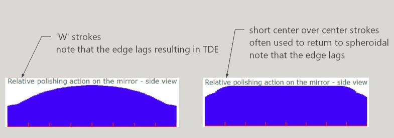
We can see from the pitch lap calculator that standard W polishing strokes, even short Center over Center strokes, polish the edge less than the center. Accordingly, the quickest fix for Turned Down Edge, indeed, overcorrection in general, is a reverse parabolizing stroke, ie, tool on top.
For more on parabolizing and the Matching Ronchi and Ronchi Tape Band Tests, see:
The Ronchi as part of the parabolizing process
Using the mirror surface profile
The Matching Ronchi Tape test
Low order or primary astigmatism is caused by the mirror's face resembling a saddle. One direction is high and the other direction at 90 degrees has low edges like a saddle. To fix, press the mirror on the tool, embedding the saddle shape into the tool. Rotate the mirror 90 degrees then execute short strokes, forcing the mirror back and forth across the tool with no rotation whatsoever and no side to side variation. After 10-20 minutes stop to check progress and repress. Repeat as needed. A few cycles should turn the mirror into an lumpy oblate ellipsoid possibly with a Turned Down Edge.
The Danjon-Couder standard has two conditions:
The Milles-Lacroix (M-L) standard says that the light rays, geometrically speaking, should all pass through the mirror's theoretical resolution disk. The M-L graphical approach to plotting the zonal readings from the Foucault test was introduced to American amateurs in the February 1976 issue of Sky and Telescope. It describes a tornado looking envelope based on the reflected light rays passing through the theoretical disk of resolution. If the zonal measurements fit within the tolerance envelope, then the mirror is judged acceptable.
The Relative Transverse Aberration (RTA) standard says that light rays reflecting from the mirror should pass within the mirror's theoretical resolution disk. Here, longitudinal slope errors along the mirror's axis are computed or measured at right angles, or transversely to the mirror's face. A passing test score is 1.0 or less. I find the weighted RTA (WRTA) useful for the same reason that RMS is more useful than P-V.
My Ronchi Calculator can be used to assign a rough wave rating.
The real finish line though is subjective. I work a mirror until I cannot make it better. I know that if I stop short, allow what I optimistically think is an acceptable error, that I will not be happy long term looking through the eyepiece. Accordingly, I always star test at the final stage so that I know exactly what I will be getting. Only then do I stop and move on to building the tube assembly and mounting.
Send off to an aluminizer or home silver per the Oregon Scope Werks silvering process.
David Davis' 16 F3
Rob Brown's 16.25 inch F3 3/8 inch thick

Peter Pekurar's 16 inch F3 1/2 inch thick

Rod Brackenridge's 14 inch F2.9
Howard Banich's 30 inch F2.7 x 5/8 inch thick
Also see my meniscus mirror page where I list more meniscus mirrored telescopes.
eod